

In AnyLogic, you define stairs connecting two floors using nodes, see the demo model below.
Demo model: Stairs Open the model page in AnyLogic Cloud. There you can run the model or download it (by clicking Model source files). Demo model: StairsOpen the model in your AnyLogic desktop installation.Let’s explain how you can bring the same logic into your model.
Usually when you develop a pedestrian model, you have a layout of the simulated building (station, museum, stadium, etc.).

First, you need to draw the area and place it exactly over the stairs area on the drawing.
Draw the stairs area
- Drag the Rectangular Node
 element from the Markup section of the Pedestrian Library palette onto the graphical editor, over the layout.
 - Resize the node as you need. Finally it should lie exactly over the stairs area on the drawing.
The next thing we need to do is define the slope angle for this node.
Define a slope for the node
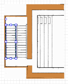
- To make the node sloped, first select the Slope for pedestrians option in the node’s Position and size properties.
- You will see the slope line appeared inside the node in the graphical editor:

- In the graphical editor, adjust the slope line’s direction. The line should point exactly in the Z-coordinates growth direction.

- Now we need to define the stairs slope itself. Usually you know either stairs slope angle (case a on the figure below), or the height between the levels (case b).
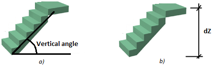
- Click the slope line and tune it to define the required slope.
- If you know the angle value (case a), leave Define slope as: angle option selected and specify the angle value in the Vertical angle control below.
- Otherwise, if you know the height between the levels (case b), choose guiding line in the slope line’s Define slope as property. In the dZ property below, enter the height between the levels, in pixels. Then direct the slope line in the graphical editor so that in XY plane it lies parallel to the stairs area direction.
If there are several levels in your pedestrian model, and you want pedestrians to change the level when they climb the stairs, you need to modify the logic of your model.
Add target lines
- Switch to the lower level and add one target line there. The target line should lie within this level. In our demo model the stairsAreaShape node defining the stairs area belongs to the lowerGround. We place the exitLowerGround target line at the border of this node shape so that it touches both this node and the areaShape node belonging to the upperGround level.
- Switch to the upper level and add another target line there. It should match the first target line exactly.
Modify the flowchart
- Add PedChangeLevel block to the flowchart. Place it before the block that operates on the new level (in the given demo model we have placed this block before the pedGoTo block whose Target line exitLine resides at the upperGround level).
- Navigate to the properties of the block and select two target lines that you have previously drawn, in the Exit line on current level and Entry line on new level fields.
We have described how to add the inclined plane that will define the staircase logically. But if you need to add 3D animation, you have to draw stairs manually.
Demo model: Stairs Open the model page in AnyLogic Cloud. There you can run the model or download it (by clicking Model source files). Demo model: StairsOpen the model in your AnyLogic desktop installation.In the given demo model the stairs are drawn using the rectangle shape. You can find it in the Projects view here: Main > Presentation > level > rectangle. If you open its Advanced properties, you will see that the shape is replicated. The Replication property is set to 25, so at runtime 25 copies of this shape will be created, corresponding to 25 stairs of our staircase.
In this example, the shape’s Height defines the staircase width: 98 pixels. Each stair must have its own X- and Z-coordinate, that’s why we use dynamic expressions for the coordinates that return individual values for each copy of the replicated shape (stair):

In the expressions, we use the local variable index, which is the zero-based index of the current copy of the replicated shape: 0, 1, 2, ... 24.
X: 270 here is the X-coordinate of the shape and the first stair, and we shift each successive stair by 10 pixels (stair’s depth defined as Width).
Y: The height between the levels in this model is 100 pixels, so since our staircase has 25 stairs, we shift each stair by 100/25, i.e., 4 pixels.
That is how we finally get the desired 3D appearance.

-
How can we improve this article?
-